
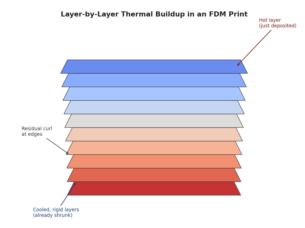
Think about the last time you baked a big sheet of cookies and watched the edges curl up before the center had even set. That’s a heat problem, not a dough problem, and it turns out 3D-printed plastic parts warp for almost the same reason. As one layer of hot filament cools and shrinks while the layer beneath it is already rigid, the part pulls itself out of shape. Print simulation software exists to catch that curl before it happens, modeling the thermal history of a print so an engineer can fix the geometry, the orientation, or the toolpath before a single gram of filament is wasted.
The physics behind this is genuinely elegant once you see it laid out. Semi-crystalline polymers like PLA and PETG shrink as they crystallize on cooling, and that shrinkage isn’t uniform across a part’s height or its raster pattern. Researchers using COMSOL to model FDM builds found that print orientation and bed temperature change how much a part distorts, because they control how evenly heat leaves the structure as printing proceeds (ScienceDirect). Even the direction you lay down each infill line matters more than most hobbyists assume; a simulation study found that when raster lines run parallel to a sheet’s diagonal, warping gets noticeably worse than when they run parallel to an edge (ScienceDirect).
So how does the software actually see this coming? Most tools use a technique called “birth-death element” analysis, which is a fittingly dramatic name for something fairly intuitive: the simulation adds material to the model layer by layer, exactly as the printer would, tracking temperature and resulting stress at each step rather than treating the part as one solid block from the start. A thermal-structural coupling study built this way was able to predict both the direction and rough magnitude of warping in an FDM part well enough to guide real print settings, not just illustrate the problem in the abstract (PMC). It’s a bit like a weather model that doesn’t just say “it’ll be cold,” it tells you where the frost is going to form.
Where this gets more interesting is what’s happening at the frontier of the field right now. A recent systematic review of thermal prediction models for FDM tracked a shift away from pure finite-element simulation and toward physics-informed machine learning, essentially models that learn from thermal camera data during real prints and use that to correct or speed up the underlying physics, aiming at something closer to a live digital twin of the build (ScienceDirect). That matters because full thermomechanical simulation is computationally expensive, often too slow to run before every print on a desktop machine. A hybrid model that’s been trained on enough real thermal histories can approximate the same prediction in a fraction of the time, which is the difference between a tool a materials lab uses and one that shows up as a “preview warp” button in consumer slicing software.
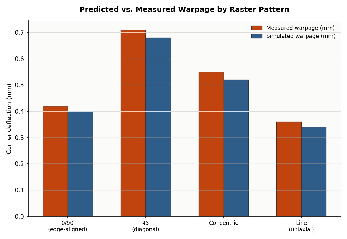
None of this means simulation has fully closed the gap between prediction and reality. Material behavior varies between filament batches, print beds don’t heat perfectly evenly, and a model tuned for PLA won’t necessarily transfer to a fiber-reinforced composite without new calibration. But the trend line is clear: what used to require an expensive failed print and a guessing game about which variable to change next increasingly shows up as a color map on screen before the nozzle ever heats up. If you’ve ever nudged a slicer’s bed temperature or brim setting because a print curled at the corners, you were making by hand the same correction these models are learning to make automatically, just with a lot less data and a lot more trial and error.