
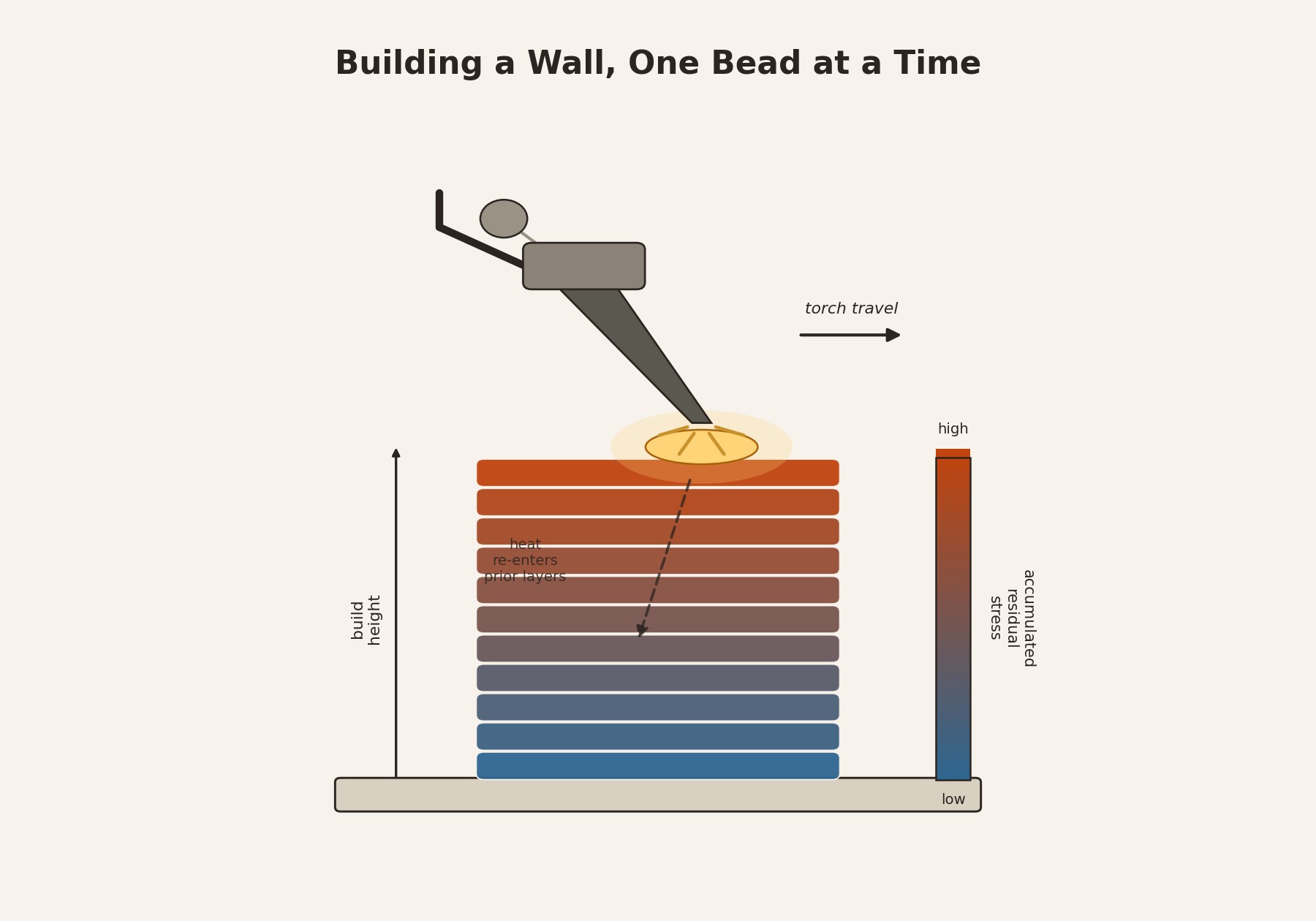
 Each new bead reheats the layers beneath it. The heat has to go somewhere, and where it goes sets both the stress state and the grain structure of everything already built.
Wire arc additive manufacturing builds a metal part the way a welder builds a bead: one pass at a time, except the passes stack into a wall instead of joining two plates. A robotic arm or gantry feeds solid wire through a welding torch, strikes an arc, and drags a molten pool along a programmed path, laying a new layer on top of the last one before it has fully cooled. Swapping a laser and powder bed for wire and an arc is a small mechanical change with a large consequence. It is the single choice that lets WAAM scale to parts a laser system could never build.
Arc welding delivers far more energy into the workpiece than a focused laser spot does, and that heat input is what sets the deposition rate. A gas metal arc process typically lays down two to eight kilograms of wire an hour, with some high-output variants reaching fifteen, against roughly a tenth of a kilogram an hour for laser powder bed fusion melting one thin track at a time (MX3D). The same energy advantage that speeds deposition also sets the resolution floor. A millimeter-scale weld pool cannot trace the fine internal channels a micron-scale laser spot can, so WAAM parts are built oversized on purpose and machined down to final form rather than printed net shape.
That same large, slow-moving heat source is also what drives the process’s defining problem. Each new bead reheats the metal beneath it well above its stress-free temperature, and as it cools it contracts against layers that have already solidified and partially cooled, so it cannot shrink freely. The result is a stress field that trends tensile near the most recently deposited surface and builds with wall height as thermal cycles accumulate through the part. Left unmanaged, that stress can climb past the material’s yield strength, and once it exceeds the ultimate tensile strength the part cracks outright rather than merely distorting (Jin et al., 2020).
Heat flow shapes more than the stress field. It shapes the metal’s grain structure too. Solidification morphology is governed by two competing quantities at the liquid-solid interface: the thermal gradient G and the growth velocity V. A high G relative to V favors long columnar grains that grow straight up the build direction, chasing the steepest temperature drop layer after layer. As deposition continues and the layers below retain more residual heat, G falls relative to V, and the solidification front can nucleate new grains ahead of itself instead of only extending existing ones, shifting the structure toward finer, more equiaxed grains.
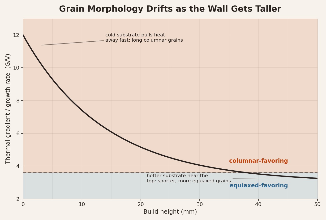 Illustrative G/V trend based on the columnar-to-equiaxed relationship described for wire arc builds: grain morphology is not fixed by alloy chemistry alone, it drifts with the part’s own thermal history.
A 2025 phase-field study of a titanium WAAM alloy mapped this G-V relationship directly against build height and validated the predicted liquid pool depths against a ten-layer titanium thin wall, showing that grain morphology is not fixed by alloy chemistry alone. It drifts predictably as the part’s thermal history changes with every added layer (Li et al., 2025).
Because both problems trace back to the same accumulating thermal history, the more effective fixes intervene in that history rather than in the finished part. Interpass cooling, simply pausing between layers, gives heat time to leave the part before the next bead adds more, damping the stress buildup but slowing the very deposition rate that makes WAAM attractive in the first place. A more direct mechanical fix is interlayer rolling: pressing each freshly deposited layer with a roller induces compressive plastic strain that offsets the tensile stress the next thermal cycle would otherwise add. Reviews of the process report that rolling also breaks up the elongated columnar structure, reducing the mechanical anisotropy that columnar grains otherwise leave behind (Jin et al., 2020).
The mechanism holds up well for the geometries WAAM is actually used for: thick-walled, near-net-shape structures like ship propellers, pressure vessel nozzles, and structural brackets, where a few millimeters of machining stock absorbs both the surface roughness and the stress relief in one pass. It breaks down for anything closer to net shape, where there is no material margin left to machine away a distorted surface or a residual stress gradient. That constraint, not deposition rate or feedstock cost, is what currently keeps WAAM confined to the large, simple parts it already does well and out of the fine-featured ones laser processes still own.